The Intake Manifold
The intake manifold was a hell of a thing to build from scratch....
Those close to me know that I only have 1 good arm (maybe 2 soon... I see a doc about a shoulder replacement next week!!!). So fabricating an aluminum intake manifold from all flat-stock 6061 was quite a challenge.
My father and I went through quite a few different prototypes. We manually cut out the base plate (to cover the oil valley) and the actual flanges that bolt to the heads using an end mill. Once we had a rough cut of those, we were able to prototype an intake manifold using thin aluminum and masking tape.
To get the proper shape for the runners, I created a wooden form that perfectly matched the shape of the port on the head, then clamped a piece of Aluminum to it and used a mallet to form the aluminum to the shape of the wooden form.
Once we had the runners formed, we needed to cut out the ports in the Intake manifold flanges. To do that, we simply used a large hole saw to cut the top and bottom of each port out, then used a hack-saw to cut down from the top hole down to the bottom. We then took a larger rotary file in a air-grinder and shaped the ports to perfectly match the intake ports on the head and the newly formed runners.
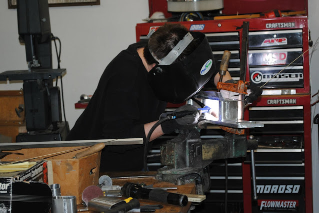
Since we only have a 180 amp TIG machine, we decided that welding the runners directly to the flat surface of the head flanges was not going to work. So we used the end mill again to remove 1/8" of material from the entire flange except around the ports... this left us with a really nice raised surface to weld to that closely mimicked a butt-weld.
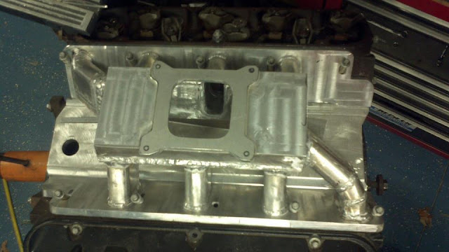
Next up we drew out a plate that would make up the top of the intake manifold and would incorporate a raised carb flange into it. We used the end mill to remove material from the flange to create the raised surface of the carb flange.
Due to the offset port design of the Gen VII big block, we had to run one runner from each head into the very end of the plenum. This forced us to use a slightly longer port for those two cylinders, but we attempted to compensate for that by slightly increasing the size of the port on the inside of the plenum (by allowing the runner to intersect the plenum at an angle).
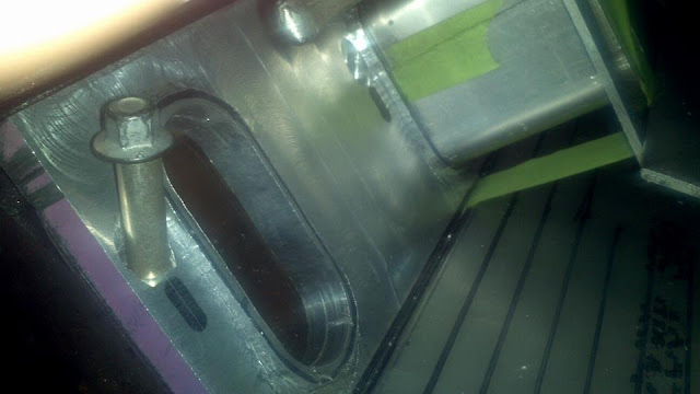
Once we completed the last two runners and finish welded the runners and plenum, we decided to add a breather to the base plate that would double as a filler neck for the oil. We took a piece of 2" diameter 1/2" wall aluminum tubing and used a lathe to form the outside. We created a step at the bottom so 1/2" of the tube slides into the hole in the base plate to create a tight fit. Then on the other side we created a small groove inside the filler neck for the o-ring on our K&N breather filter to slide and lock into.
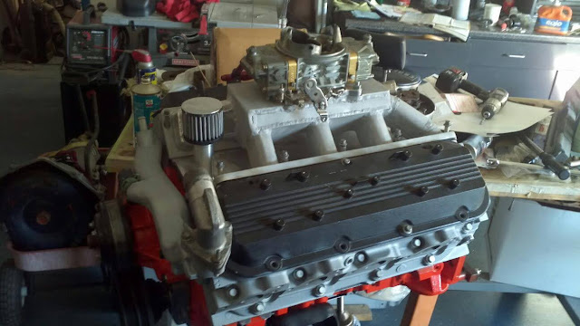
All that is left now is to affix the base plate to the flanges that bolt to the cylinder heads. We are still debating how to do this, because we know that if we TIG weld them together, it would severely warp the entire manifold. We had considered drilling the block and inserting dowel pins to keep the base plate in place, but I think we have decided to simply drill and tap the flanges and base plate and create a nice aluminum strut that will hold all 3 together.
Those close to me know that I only have 1 good arm (maybe 2 soon... I see a doc about a shoulder replacement next week!!!). So fabricating an aluminum intake manifold from all flat-stock 6061 was quite a challenge.
My father and I went through quite a few different prototypes. We manually cut out the base plate (to cover the oil valley) and the actual flanges that bolt to the heads using an end mill. Once we had a rough cut of those, we were able to prototype an intake manifold using thin aluminum and masking tape.
To get the proper shape for the runners, I created a wooden form that perfectly matched the shape of the port on the head, then clamped a piece of Aluminum to it and used a mallet to form the aluminum to the shape of the wooden form.
Once we had the runners formed, we needed to cut out the ports in the Intake manifold flanges. To do that, we simply used a large hole saw to cut the top and bottom of each port out, then used a hack-saw to cut down from the top hole down to the bottom. We then took a larger rotary file in a air-grinder and shaped the ports to perfectly match the intake ports on the head and the newly formed runners.
Since we only have a 180 amp TIG machine, we decided that welding the runners directly to the flat surface of the head flanges was not going to work. So we used the end mill again to remove 1/8" of material from the entire flange except around the ports... this left us with a really nice raised surface to weld to that closely mimicked a butt-weld.
Next up we drew out a plate that would make up the top of the intake manifold and would incorporate a raised carb flange into it. We used the end mill to remove material from the flange to create the raised surface of the carb flange.
Once we completed the last two runners and finish welded the runners and plenum, we decided to add a breather to the base plate that would double as a filler neck for the oil. We took a piece of 2" diameter 1/2" wall aluminum tubing and used a lathe to form the outside. We created a step at the bottom so 1/2" of the tube slides into the hole in the base plate to create a tight fit. Then on the other side we created a small groove inside the filler neck for the o-ring on our K&N breather filter to slide and lock into.
All that is left now is to affix the base plate to the flanges that bolt to the cylinder heads. We are still debating how to do this, because we know that if we TIG weld them together, it would severely warp the entire manifold. We had considered drilling the block and inserting dowel pins to keep the base plate in place, but I think we have decided to simply drill and tap the flanges and base plate and create a nice aluminum strut that will hold all 3 together.


Comments
Post a Comment